Three different motors testedLRK350-20-15w, -13w,-11w
Lots of measured data from the LRK350-20-15w can be found here: LRK350-20 with rotating shaft, design, realisation, measurement We used these data to calculate and build a 13 turns motor for Jochen (10 Cells 300 W with 14x8 prop) and a 11 turns motor for myself (8 Cells 250 W with 14x8 prop), and then made some extended measurements, in order to test the algorithms from How many turns does my LRK350-20 motor need? . This time I did not register the data by simply reading the displayed values, but let the Data Logger do the work for me. One could say the 15-turn motor was a trial run and the 13 and 11-turn motors are the final product, these motors should be very useful to us for many years to come.
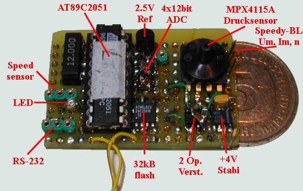
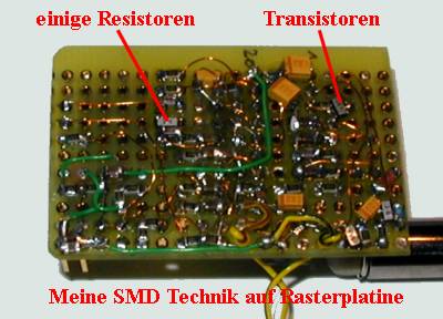
This is my 5th Data Logger; I soldered it together in a hurry to record flights with the LRK motors. The program is not new; I just adapted an existing one. The beauty of this construction is that it can just as well be used at home. Just connect it to the PC and almost immediately data from the Speedy-BL Controller (Volts, Amps, RPM) are in the box. When measuring stronger motors in the garden data is temporarily stored in Flash-Memory. Speed-sensor and altitude-sensor are simply ignored.
Technical specifications of the Data Logger for measuring motors: · Every number is the mean value of 16 measurements · These 16 measurements can be made in 0,125s to 64s intervals · Voltage accuracy: 0,002 V measured at the controller · Current accuracy: 0,01 A measured over a 2 milliohm Shunt in the Speedy-BL · Rotational speed 1/7 rpm, measured at the MOSFET-driver It is very important to measure the rotational speed accurately, as it goes into the calculation “cubed”. The data is sent to the PC over the RS-232 serial port “live”. When measuring is complete the results are processed with Matlab. This motor has the lowest RPM/Volt but also the highest Ri @ 36 milliohm. These data were not gathered with the Data Logger but with “classical” measuring equipment (Voltmeter, Amp meter, Oscillograph). Unfortunately all I had available for the measurements at the time was a5-15 V, 30A power supply). I also used 8,10 and 12 cell power packs, but these results were not interesting, as only one voltage is considered. Graphs or Tables? I prefer graphs to tables, mainly because one can immediately see how a motor behaves over a range of voltages. It is immediately obvious if the chosen cell count will be sufficient and if enough power will be left when the power pack is almost empty. All measurements were made with Aeronaut propellers. The most important graph: how much power is taken from the motor. What prop? Every circle on the graph represents a complete measurement.
Also interesting: What is the current @ 8V with an Aeronaut 18*11 folder?
Lots of people prefer RPM to current or power. When a 14"x8”spins @ 5.500/min they know how things are looking
I often use this last graph for a short check before a flight. At this time volts and amps cannot be easily measured to calculate the power. Measuring RPM with an optical tachometer is quite useful to check if enough power is available.
This LRK 350-20-13 motor was designed to get an ASW27 (3.800g) in the air comfortably with a 14"x8". On Sunday 2 September 2001 the ASW was launched with a Telario-Talk variometer on board .The climb was about 20% better than with the previous motor/prop combo (Ultra 1300/10), while the runtime from the 10-cell battery pack remained the same. The motor was measured with different Aeronaut (a) and Graupner (g) folding propellers, with the Data Logger. For convenience, the single lines are marked with the prop sizes. The line colour is the same for all graphs of the same motor. Every circle on the graph represents a complete measurement. The P(u) Graph was lost, will be restored later. Lots of people prefer RPM to current or power. When a 14"x8”spins @ 5.500/min they know how things are looking!
I often use this last graph for a short check before a flight. At this time volts and amps cannot be easily measured to calculate the power. Measuring RPM with an optical tachometer is quite useful to check if enough power is available.
This LRK350-20-11w is a rather hot motor already. Ri only 15 milliohm, this makes for a rather large Max. Eff. range. Max. Eff. is also rather high. The goal was 250 W @ 8 cells, without getting hot. The motor was measured with different Aeronaut (a) and Graupner (g) folding propellers, with the Data Logger. For convenience, the single lines are marked with the prop sizes. The line colour is the same for all graphs of the same motor. Every circle on the graph represents a complete measurement.
And the current for every prop:
Lots of people prefer RPM to current or power. When a 14"x8”spins @ 5.500/min they know how things are looking!
I often use this last graph for a short check before a flight. At this time volts and amps cannot be easily measured to calculate the power. Measuring RPM with an optical tachometer is quite useful to check if enough power is available.
A few measurements in table form Here’s a brief reminder of the known motor parameters: We connect the motor to a voltage Um and load it with a propeller LS. The current Im.is flowing trough the motor. The propeller spins at n RPM Um
– Motor voltage Every motor can be described with a few characteristic numbers, among these are: Io – Idle current (Goes up with voltage, mostly linear) Ri – Internal resistance, more or less constant
A few measurements that were shown above as curves can be found in the tables below. The most important column is the no-kns. Almost constantfor the 3 motors.
ns as a function of the motor current ns(n,Im, ...) –RPM/Volt, depending on n itself and Im etc The ns(Im) is calculated as the RPM/Volt ,having subtracted the voltage loss over Ri first. U = Um - Im * Ri ns(Im) = n / (Um - Im * Ri) = n / U
A “trend” line was fitted through the measured data and continued to Im=0. This line is independent from the used props LS (small or large) but dependent on the number of turns. The interesting thing is that the slope of this line is always around -4.
W, a characteristic motor parameter independent of the number of turns I’d like to introduce a new characteristic motor parameter. It only depends on the construction of the motor (Rotor dia, Stator length, Air gap etc.), but is not influenced by the number of turns no=ns (0) * N (number of turns) is constant for a given motor, and is not dependant on the winding or the magnet wire gauge.
The W-number for the 3 motors with different number of turns, but the same rotor and stator is:
It looks as if the W-number increases to about 16.000 for a 12 mm Stator length and decreases to about 8000 for a 24mm stator length. I will do more research on this as soon as I measured the 12 mm LRK. Please send me all the measured data from your own LRK’s so we can refine our model. Perhaps we can also include the diameter into the equation. How you can use this W-number to wind a motor for a specific task is shown in : How many turns does my LRK350-20 motor need?
|
|||||||||||||||||||||||||||||||||||||||||||||||||||||||||||||||||||||||||||||||||||||||||||||||||||||||||||||||||||||||||||||||||||||||||||||||||||||||||||||||||||||||||||||||||||||||||||||||||||||||||||||||||||||||||||||||||||||||||||||||||||||||||||||||||||||||||||||||||||||||||||||||||||||||||||||||||||||||||||||||||||||||||||||||||||||||||||||
.gif)
.gif)
.gif)
.gif)
.gif)
.gif)
.gif)
.gif)
.gif)
.gif)
.gif)