If a proof was needed, here it is: The model builders of today are not reduced to buyers of the precious and expensive as the world have tried to tell. The unexpected lively echo of the suggestions for the do it yourself motors shows, that even in the time of the ARF models and everything can be bought ready, many model flyers still want to be creative and prepared to do some experimenting.
Insurmountable problems seems
to arise only when the individual collides with a sales organisation
programmed for efficiency, like when someone tries to buy small
numbers of goods. The getting of stator pieces and magnets have
been nearly impossible. More on that later. And of course when
trying to build the motor, a number of questions turned up not
answered enough in the first article. This theme will be dealt
with now.
Questions, tips and concrete instructions
Let us start with a shortage in the theory. Nothing was told
of the principle of magnetic feed back. A lot of people have
asked if one could not just cut away the unused stator teeth.
No, please no. Contrary to a common two-pole
machine the magnet flow from one coil, in the Torquemax motor
(and in four-pool motors), do not go diagonal through the motor
(quite a long way) but in the form of a W. Like the diagram
shows, the magnetic flow goes from the coil over the rotor magnet
and then in two halves through the teeth without windings and
back to the coil.
While the stators blades are cut to 12 and there are 14 magnets, there is no 'hard raster ring' like in other BL motors. Stator blades specially cut for this kind of motor should really have thinner unwound teeth. However there is no need to reduce them with a file.
Winding schematic
 The winding diagram with the very
abstract winding
scheme produced a number of questions.
The winding diagram with the very
abstract winding
scheme produced a number of questions.
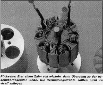
In Principe, start to wind each tooth fully with the wanted number
of turns before the wire is brought over to the opposite tooth.
And every coil must have the same number of windings. Here some later schematic. If not, the motor
will run like a tandem bike where the runners disagree on the
speed. When the windings are ready, it is not possible to count
the number of turns. That is why it is recommended to measure
the inductivity of the coils. Conrad
(a German electronics supplier) sells a relatively economic test
instrument (LCR-Multimeter, order number 131695) which gives
a somewhat limited but sufficient result. And after each winded
coil it is necessary to check for shorts to the stator metal
parts. This could even happen when finally assembling the motor,
if the wire is allowed to scrape on some of the metal parts.
When running motor looks like a tap-dance, the cause of this
is usually an undiscovered short between windings or to the case.
That's why it will do no harm to pot the windings in epoxy when
they are ready and tested. And please note, not every controller
can survive with part defect windings (for
the first testing use current limited power supply , don't use
batteries, that can supply even 100A end destroit your motor,
P.R.)
Magnets
 Also
the gluing of the magnets needs some experience in dealing with
industrial glues. A condition is of course the cleaning and removing
of grease from the metal parts with acetone or something like that. A problem can be that
LOCTITE
is an aerobic glue which only hardens when there is no air. As
the rectangular magnets only touch the round iron ring in the
corners, the gluing area will be very small. It can do no harm
to improve the gluing with some cyano in the gaps between the
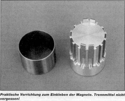
corners. The gluing with UHUplus
endfest 300 (a high quality German
epoxy glue) have also proven itself, the gluing is tempered in
the bread oven set to a temperature of 80
- 100 ° Centigrade. If using
epoxy one needs help tool like shown above. Can be made from
aluminium or Delrin.
Also
the gluing of the magnets needs some experience in dealing with
industrial glues. A condition is of course the cleaning and removing
of grease from the metal parts with acetone or something like that. A problem can be that
LOCTITE
is an aerobic glue which only hardens when there is no air. As
the rectangular magnets only touch the round iron ring in the
corners, the gluing area will be very small. It can do no harm
to improve the gluing with some cyano in the gaps between the
corners. The gluing with UHUplus
endfest 300 (a high quality German
epoxy glue) have also proven itself, the gluing is tempered in
the bread oven set to a temperature of 80
- 100 ° Centigrade. If using
epoxy one needs help tool like shown above. Can be made from
aluminium or Delrin.
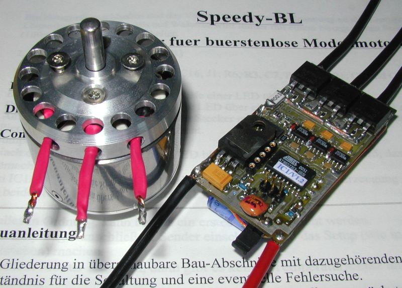
Controller
Some motor builders tried to use other controllers than the ones mentioned in the first article. In principle the Torquemax will run with any controller made for a sensorless motor. However it could be a problem with the limit frequency. Our 14-pole outside runner needs for every revolution 7 electrical switching cycles. If the controller have a frequency limit of 50 kHz, the rpm limiting will cut in at around 7000 rpm.
Many times have also the question been asked about a do it yourself controller for the Torquemax. Here come first a careful warning. A controller for a brushless controller for a sensorless motor is a lot of work and can in no way be compared to a controller for ordinary brushed motors. A project like this needs expertise in circuit design and in software programming and must be made in SMD technique on several circuit boards to keep it light and compact enough, not to loose the weight advantage of the system. But the author is happy to tell that some individuals already are working in this direction. However, taken from experience, it will take some time yet.
This do-it-yourself controller exists and works very well. It allows even more settings than other, more expensive controller (measurements (goto Vorzuendung) on my German HP). However soldering of these small SMD parts on the tiny PC board isn't easy and shouldn't be taken as a first excursion into SMD technique. You need osciloscope to find out, why it isn't working after you've put some solder bridges on the board. MEGRA is selling the kit. P.R.
Propeller
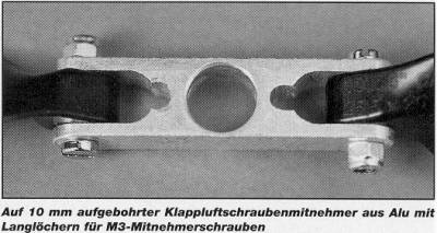 Questions
where asked, how to adapt an ordinary centre piece for folding
propellers to the Outside Runner. This will be no problem. The
8 mm hole in an ordinary 12 mm wide centrepiece is carefully
opened up to 10 mm. As shown in the picture enough material is
left. For the attachment screws, two slots are made with a file.
If one have built a motor with a 12 mm boss, the plastic centre
piece from Graupner can be used with the hole opened up.
Questions
where asked, how to adapt an ordinary centre piece for folding
propellers to the Outside Runner. This will be no problem. The
8 mm hole in an ordinary 12 mm wide centrepiece is carefully
opened up to 10 mm. As shown in the picture enough material is
left. For the attachment screws, two slots are made with a file.
If one have built a motor with a 12 mm boss, the plastic centre
piece from Graupner can be used with the hole opened up.
Harder than anticipated had been the process of getting magnets and stator disks. The "Supply Service" set up by the author can not complain of not being used and even run out of supply itself. Regrettably some of the suppliers did not stand by their words. Stator disks of 32 and 35.5 mm were hard to get. Things got better. Stator disks of 34.5 mm diameter can be bought from the firm Leaner Motoren Technic (Phone (0)89-6019922 with the country code for Germany first). This disks are of best quality (0.3 mm) and have a 6 mm hole in them. One might need an additional bushing.
Today, 6 months later, very is no problem in getting magnets and stators at BATT-MANN
And now THE BIG ONE ....
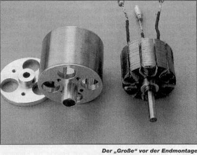 It would be punishable
to ignore the experience of logistics from the first article.
That's why the author ask for understanding why the already promised
1,000 watts motor have to wait a
while because of the material problem. The motor presented here,
the bigger Torquemax LRK 355/24 with doubled magneto length,
come however quite near this power limit. It can be built with
stator disks of 32, 34.5 or 35.5 mm diameter and with a weight
of 200 - 230 grams plays in the
same class of weight as the Speed 600 motor and will be running
at best between 300 and 600 watts. By an optimised winding and
potted in epoxy 800 watts is possible.
However one would not do this design right, only looking at the
power. The first built example with 21 turns of 0.68 mm wire
could, with 12 - 14 cells run with propellers up to 18 x 11 inches
( Aeronaut CAM-carbon), which is explained by a specific RPM
of 360 revolutions per minute and volt. As the length of the
wiring is quite long, such motors needs a good factor of winding
fullness, which this first motor did not have. With a inner resistance
Ri around 130 milliohms and an idle running current of 1.5 amperes,
this machine is best for higher voltage and lower current.
It would be punishable
to ignore the experience of logistics from the first article.
That's why the author ask for understanding why the already promised
1,000 watts motor have to wait a
while because of the material problem. The motor presented here,
the bigger Torquemax LRK 355/24 with doubled magneto length,
come however quite near this power limit. It can be built with
stator disks of 32, 34.5 or 35.5 mm diameter and with a weight
of 200 - 230 grams plays in the
same class of weight as the Speed 600 motor and will be running
at best between 300 and 600 watts. By an optimised winding and
potted in epoxy 800 watts is possible.
However one would not do this design right, only looking at the
power. The first built example with 21 turns of 0.68 mm wire
could, with 12 - 14 cells run with propellers up to 18 x 11 inches
( Aeronaut CAM-carbon), which is explained by a specific RPM
of 360 revolutions per minute and volt. As the length of the
wiring is quite long, such motors needs a good factor of winding
fullness, which this first motor did not have. With a inner resistance
Ri around 130 milliohms and an idle running current of 1.5 amperes,
this machine is best for higher voltage and lower current.
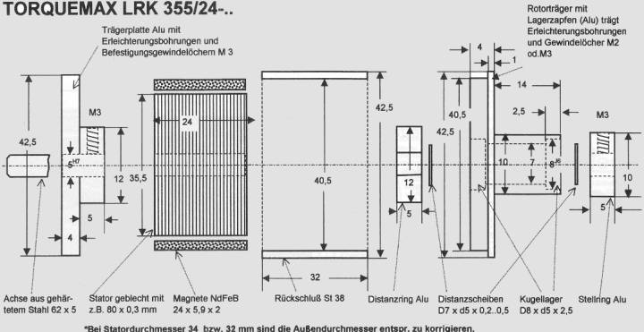
Blue prints:
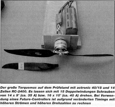 The second variant has got 15
doubled turns of two parallel 0.63 mm copper wires ( it would
be possible to get in 18 - 20 turns with this wire and with careful
winding) and the inner resistance got down to 50 mOhm (the newest LRK350-20-11 has only 15mOhms P.R).
It was also shown that it is much easier to wind, when you work
with several parallel wires. This machine got a specific RPM
of 500 revolution per minute and volt. With an idle running current
of around 2.3 amperes one got a good compromise between torque
and power. With 14 cells and a 14 x 9 inch CAMcarbon the current
was 35 amperes.
The second variant has got 15
doubled turns of two parallel 0.63 mm copper wires ( it would
be possible to get in 18 - 20 turns with this wire and with careful
winding) and the inner resistance got down to 50 mOhm (the newest LRK350-20-11 has only 15mOhms P.R).
It was also shown that it is much easier to wind, when you work
with several parallel wires. This machine got a specific RPM
of 500 revolution per minute and volt. With an idle running current
of around 2.3 amperes one got a good compromise between torque
and power. With 14 cells and a 14 x 9 inch CAMcarbon the current
was 35 amperes.
The magnets can be lined up two pieces of 12 mm length or one magnet with the dimension 24 mm x 5.9 mm x 2 mm already in stock. The first solution gives some theoretical advantage but the second one is easier to do.
It is obvious that the Torquemax thanks to the simple mechanical construction has its limit. Due to placement of bearings on one end of the motor, the mechanical stability isn't the best. By the comparatively long magnets, current peaks and also bugs in the software (the programmer is only human) can lead to bends. A bigger diameter (for example 38 mm diameter disks and 3 mm thick magnets) would in many aspects be better than longer magnets.
An important thing, not to be underrated, are the forces working on the magnets even during normal operation. If the machine is intended to run at high current (40 amps and higher) a good gluing is important. (Preferable with UHUplus endfest 300). One could also consider to make the iron tube 0.5 mm thicker. The RPM is however, provided the rotor is balanced, uncritical.
How will this story continue
The concept of the Torquemax motor is not finished yet. Thoughts of using the motor in an impeller have already been sketched up by Christian Lucas and awaits to be done. It would also be interesting to rearrange the Outside Runner a bit to permit the motor to be mounted in the usual way to a front former in a model. We are also looking into to reduce the iron losses in the motor with a quite different design. Stay tuned to LRK sites!
The HTML-editor and translater has built few motors, that are runnig very smooth at 300-400 watts.