|
 |
Die LRK-fans recognize in line c) winding A and -A. This is our 180 degree out of phase winding, that we put on opposite slots. See also here |
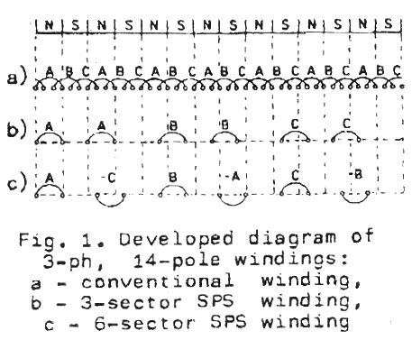
Fig. 1a shows the conventional 3-phase, 14-pole winding with one slot per pole per phase. It consists of 21 coils, embedded in 42 slots.
Fig. 1b and lc show the new winding arrangement with separated phase-sectors (SPS).
The "phase-sector" is here understood as a part of the armature in which there are only coils belonging to the same phase-winding. Fig. lb shows the SPS winding composed of three phase-sectors (with two coils in each sector) and Fig. lc the winding of six single-coiled phase-sectors. Location of the coils in a given sector can be easily determined since it corresponds with coil distribution in the conventional winding (Fig. 1a). Despite the very small number of coils in each of SPS-windings, they retain features of being the electrically symmetrical 3-phase, 14-pole windings.
The 6-sector winding in Fig.1c proves better than the 3-sector one because each phase-winding is symmetrical with respect to the machine shaft. This geometric symmetry eliminates unbalanced radial forces which may occur between stator and rotor surfaces.
 |
It could be found that the 6-sector winding is feasible only for the number of pole-pairs given by formula where k - number of coils in each sector: k = 1,2 ,3 , ...
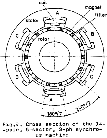
Fig.2 shows the cross section of the 14-pole 6-sector machine. The coil span is the same for all coils and is equal to the pole-pitch. However, the distance between two neighboring slots, belonging to the different phases is equal to 2*tau/3 or 4*tau/3 for (-) or (+) in equation (2) respectively. |
PERFORMANCE OF 3-PHASE SYNCHRONOUS MACHINES WITH SPS-WINDINGS
The structure of electric and magnetic circuits of the 3-ph machine equipped with SPS-winding is such that each phase is practically decoupled. so it may be considered separately. Therefore, the 3-ph machine can be represented as three single-phase machines, supplied from different phases of 3-ph source and operating on the common shaft.
The next section of the publication contains a lot of equations, that are difficult to entry into html. I skip this section.
EXPERIMENTAL MACHINE MODEL
The 3-ph. 14-pole synchronous machine, model has been designed for experimental verification of the SPS-winding configuration.
The technical data of the model:
No-load e.m.f. (Eo) = 45 V
p = 7
n = 428.6 r.p.m. at 50 Hz
l = 26 mm, D = 67 mm
air-gap = 0.35 mm
The laminated cylindrical rotor has the neodymium magnets flat-mounted on its surface, producing no-load flux density of 0.7 T. The model has been tested as generator, operating on a resistive load as well as a motor.
The next section of the publication contains some diagrams of voltage and current and discussion of harmonic content. There is also an efficiency diagram (up to 72%), cos(phi) and power diagram. The copy that I own doesn't allow reasonable copy to be made.
CONCLUSIONS
Application of new permanent magnet materials of high energy enables construction of small-pitch multipole field systems, suitable for low-speed synchronous machines. Unfortunately, construction of the corresponding small pole-pitch armatures employing 3-ph conventional windings encounters a technological barrier, as the armature teeth are getting very thin end the winding overhangs become quite complicated due to short end-connections.
Application of the proposed SPS-winding enables machine designs of approximately three times smaller pole-pitches and rotor diameters than in machines with the conventional winding. The number of slots and coils is also reduced by the above ratio, which simplifies the construction considerably, and yet the machine retain their features of being the 3-phase symmetrical ones.
A change from the rotating to pulsating
armature flux, being the consequence of application of SPS-winding,
diminishes the torque produced, but this is partly made up for
by possibility of employing higher electric loading. The SPS-machines
seem to be the most suitable to fill the gap between the conventional
and transversal-flux constructions ie for pole-pitches ranging
from 5 to 2 cm. The test of the experimental machine model generally
proved predicted features of the SPS-construction. Some further
investigations should be carried to find the optimum design.
REFERENCES
1. Weh H., Hoffman H., Landrath J.: "New permanent magnet excited synchronous machine with high efficiency at low speeds" Proc. of the ICEM, 1988, pp.35-40.
2. Schoepp K., Zielinski P.: "Low-speed AC Machines" Report SPR nr 7/91 I-29, technical University of Warsaw 1991, pp. 1-27 (in Polish)