TORQUEMAX LRK
Sensor and brushless
do-it-yourself motor
No, elektroModell 4/2000 is not the April issue but the issue of the fourth quarter of the year. The suggestion to build an electric motor yourself is not an April Fool's joke. As a matter of fact, there is not that much involved: just a permanent magnet which runs round and round in a revolving magnet field. Everything that can be worn out are two ball bearings. Only the centrifugal forces are working hard on the fitted small pieces of Neodym magnets. However with this special concept there will be no principle problems. This motor is designed as an outside runner where the parts, when running, go where they want to go. The magnets are outside and the windings in the center.
I you want to build this motor you need a metal turning lathe, or at least a friend with one and someone good at using it. It is not enough to be able to make things round--especially in the bearing area you'll need some precision. The rest of the parts not made with the lathe can be bought commercially.
Now an explanation of the name. TORQUEMAX suggests that this
a motor has been designed for torque. The LRK
comes from the designer Christian Lucas, the
elektroModell author Ludwig Retzbach
and the lathe specialist Emil Kuerfuss.
Thanks also to Walter Froeschle for the help.
Everything under control
Even a sensorless and brushless motor only works with a controller if they understand each other fairly well. It is exactly the same with commercial motors. You will notice at the start up if the two components do not like each other. However, there are pairs that work very well together even when they come from different manufacturers. The TORQUEMAX works very well with FUTURE, the controller from Schulze Electronics, thank to the new software written by Ulf Herder. The motor also seems to work well with the new actronic controller from the Koehler Brothers (also with Speedy-BL from Jo Aichinger, comment Peter R). There is no wonder that this controllers work with LRK. These controllers were designed for similar multi-pole motors.
It is helpful to first learn a bit of the different concepts of motors for electric flight. You will understand LRK and the differences relative to existing motors. The LRK concept can be viewed as an enrichment of existing concepts, not as a fear of or replacement for them.
Motor concepts
With each motor size one tries to achieve as high an efficiency as possible. This is a product of torque and RPM. In each case it is important that as little as possible of the battery power be transferred into heat. How good this will be depends on the system efficiency. However physical laws can be hard to tamper with. A step forward in one direction can mean a step back in another.
The simplest way to get high specific power is to increase the revolutions per minute. The master of this type are the two pole inside running motors from Lehner or, the modified and more easily manufactured motors from Hacker that these days consist of a big family of different sizes. In this type of motor, the windings are not done around an iron core, but are wound in the free air. This means the motor inductivity is reduced and the change of current direction can happen more quickly. And because of a rather large distance in the air (inside the motor) and a rather homogeneous magnetic flux, the iron losses in the magnets and in the outer iron parts, which increase steeply with increasing RPM, are kept within acceptable limits. Harald Konrath is trying to do the same thing in his TANGO motor, which has a rotating, iron outer cylinder. This system hasn't been very successfull due to the lack of a suitable controller. It is obvious, that the motor systems with air wound windings need a specially designed controller. A typical disadvantage in this kind of motor is the limited possibility to cool the Neodym magnets residing inside of the motor. And of course, the torque of the motors tested thus far is not enough for the direct drive of big propellers.
A very different approach has been taken by the multi-pole
motors from the Koehler and Plettenberg firms. In the Koehler actro outside runner, the 8-pole concept
gives you hight torque and the rotating externally attached magnets
cool themself. A disadvantage is the hard to wind, very special,
laminated iron stator core and the relatively long path in the
iron for the magnetic flux. Plettenberg managed to lessen this
last drawback a bit with his 10-pole, washing machine, motor.
This one is however even more difficult to build and does not
use all of the available inner space. The principle of internal
running magnets with a big rotor diameter also gives large centrifugal
forces. The magnets must be tied down to stand high RPM.
Thus, high torque machines are more expensive to build and in a direct comparison with high speed runners give a bit lower degree off efficiency, but only as long as you don't include a gearbox. High speed motors with a gearbox, on the other hand, have proven themselves to be quite good, especially in competitions. Still, a direct drive motor needs less maintenance and is in reality no less efficient counting with a gearbox loss of at least 5 %.
The "ATDI" Motor
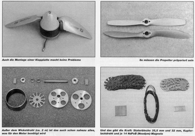
The do it yourself motor presented here is a 14-pole outside runner. Together with a 12 part stator you get a high overlap for each angle of rotation (a small distance between poles means a high pulling power). The special thing with this design is a very compact size and, thus, a low weight. The unusually high number of poles gives high torque with few windings, which means low specific RPM by a low inner resistance. The machine gives you not only a high power per weight (watts/kilogram) but also a prominent torque per weight (Newton metre/kilogram). One could speak of a TDI kind of electric motor (In Germany Turbo-Diesel-Inject stands for the outstanding engine with high torque). Also the degree of efficiency of this self made motor is in no big way worse then that of series-built motors. However the reader must understand that a design made towards torque cannot also offer a high efficiency. Test runs with propellers of known power consumption (Aeronaut-CAM-Carbon-Series) for the labor-intensive prototype meaured an efficiency of just a bit lower than 80 % but with a broad maximum. More exact values could not be obtained as existing test equipment made for inside running motors do not fit this new motor concept. The main source of losses in this simple motor lies in the iron loop. It could certainly be optimized. The copper losses are less important
The Outdoor solution (motor outside of the fuselage)
 The stator is based on 12-part
metal stampings as used by standard brushed motors from firms
like Buehler, Plettenberg, Ultra and also by Koehler´s
Newtor. The trick here: Only every second anchor part is wound.
After a quick attempt, I found it easy to do yourself as there
are only a few windings to do. There is no transfer of windings
to the next anchor part. The bulges of copper on the ends of
the stator are in this way held in limits. This helps to make
the TORQUEMAX-machine so compact, it do not have to be built-in,
in most cases it can be built-on to the model. This helps to
get the centre of gravity in place as both first prototypes only
had a weight of 128 grams (4.5 oz).
They where designed for power output in flight of around 450 watts but have also survived powers
of 550 - 600 watts in tests and were still surprisingly cool.
The stator is based on 12-part
metal stampings as used by standard brushed motors from firms
like Buehler, Plettenberg, Ultra and also by Koehler´s
Newtor. The trick here: Only every second anchor part is wound.
After a quick attempt, I found it easy to do yourself as there
are only a few windings to do. There is no transfer of windings
to the next anchor part. The bulges of copper on the ends of
the stator are in this way held in limits. This helps to make
the TORQUEMAX-machine so compact, it do not have to be built-in,
in most cases it can be built-on to the model. This helps to
get the centre of gravity in place as both first prototypes only
had a weight of 128 grams (4.5 oz).
They where designed for power output in flight of around 450 watts but have also survived powers
of 550 - 600 watts in tests and were still surprisingly cool.
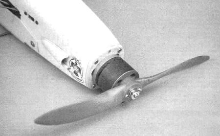
Healthy for these motors is also the lot of fresh air that blows over it which can not be avoided when working so near the propeller. The propeller sits directly on the rotor, one does not need an adapter. The propeller shaft hole must be redrilled to a diameter of 12 millimetres and two additional 3 millimetres holes added. Centre pieces for folding props must be modified in the same way. At last, it must be possible to make a spinner with a fully integrated TORQUEMAX motor (has not been tested yet).
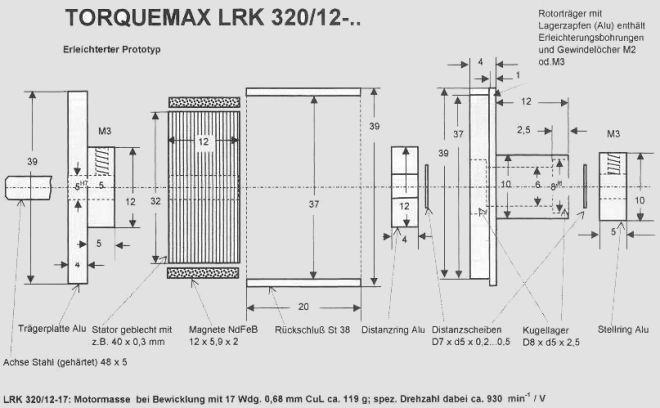
The author does not look upon this suggested design as the optimal version. It is possible to save weight in several places without losing stability. By the design shown here (TORQUEMAX LRK 320/12-17) the weight is 119 grams even with a greater magneto length. Modelling weight watchers with a desire to experiment will find more opportunities to save weight. Consider milling out the end shields, by using a hollow shaft or by partly changing some aluminium parts for carbon composites. An all out effort would be to leave out the rear shield and just glue the rear shaft into the fuselage.
In a later issue it is planned to show a motor with a greater stator diameter and/or greater magneto length (for up to 1000 watts) which is being developed and tried right now. Problems of special installations and possibilities for the use will also be discussed
And now back to school for some theory
In a time when almost everything is possible to buy ready made, it only makes sense to build technical components if in this way, they can be better tailored to your needs. Here are some tips on how you can calculate your special motor. Here only the magnetic forces are allowed for. The electrical values are left for later. As Master propellers are used the CAMcarbon serie from Aeronaut not only because of their known quality, but mostly because the company publishes power values for the propellers.
The power F from the magnetisized pole working on the rotating magnet is proportional to the magnetic flux B in the air gap and the area of iron A and equals:
F = A x 4 B ^ 2
For the Neodym magnets, assuming (conservatively) that B = 1 T, places the force at 4 N/cm^2. As 65 % of the outer surface will be covered with magnets (otherwise the individual poles would be too close together), we will assume we have just 0.65 x 4 N/cm^2 = 2.6 N/cm^2. A sample model with a 32 mm stator diameter and 10 mm magnet length has the following area.
A = 2r x 7t x I = 10,05 cm2
The force in the air gap is thus:
F x A = 26 N
The rotational moment of the motor with a 16 mm stator radius can be calculated as:
M = F x r = 26 N x 0,016 m = 0,42 Nm
The motor can theoretically give this
torque at maximum load at any running RPM.
This means: A torque of 0.42 Nm is needed to run a Aeronaut CAM-Carbon propeller, 9.5 x 5 inch at a speed of 15 287 rpm. By an 8 x 5 from the same company, the torque can be calculated to give 21 444 rpm. If you take a 16 x 10 you get 4 342 rpm. For a motor in direct drive, this is a lot of revolving power for its 120 gram weight, about the same weight as a weak Speed 480 motor.
The power the motor gives is of course depending of the number
of rounds per minute
|
|
|
|
|
|
|
|
|
|
|
|
|
|
|
|
|
|
|
|
|
We don't need to go so far, but with efficiency in mind, we'll
stay below 15,000 rpm, even if we'll use only about 80-90% of
maximal torque.
Calculation of windings
As with every other electric motor, the input power by the TORQUEMAX is given by the formula U x I where more voltage, U is better then more current, I. The class of voltage is given by the number of windings. This is best found by an empirical method. Wind one tooth of the anchor with for example 10 turns of wire. Assemble the motor and hold it in the chuck of a drilling machine. Let it run at medium speed and measure number of revolutions (put a reflective mark on the motor case) and the given generator alternating voltage. The last value must be doubled as later two anchor teeth will be in series. Add around 15 to 20 % to cover running losses. If you get a measured voltage of 3 volts the motor is good for around 7 volts. A 7-cell motor needs to have 10 windings. If you want a motor for 14 volts, use a 20 turn winding and so on.
The winding can go wrong
If you could not do anything wrong, it wouldn't be much fun. However putting the stator and the winding together is challenging. If possible, the packet of stator blades should consist of many thin metal blades. The number is given from the desired length and the available magnet length. This should not be greater then 70 % of the stator diameter (L/D<0.7).
The stator blades, with a 5 mm hole in them, are stacked on the steel shaft and glued with Loctite 601. Then break the outer edges with a fine file. This will help to avoid shorting the windings to ground later. After that the space for the windings must be isolated. Some use a dried layer of thick cyano. An isolating lacquer alone is not enough to prevent shorting. Motor builders use thin strips of heat resisting foils that are cut oversize and put into the slots overlapping the ends. One might also use heat resistant self adhesive tape eg GOLDfix-Kapton. Even with all this precautions one have to check for shorts with a volt/ohm-meter.
Despite considerable practice, winding the coils has not become one of the author´s favourite pastimes. He has also noted that dull television programs are not a suitable entertainment while winding. You really need to be in complete isolation. From the motor current´s point of view it is not important if the windings look good. It also does not mean much from a mechanical view. But the motor really likes the windings to all have the same number of turns. And in the interest of efficiency it does not hurt if at least the first number of turns are put in side by side. This takes time and give you sore fingers, but it will be rewarded.
With this size of motor, a wire with a polyamidlacquer isolation to take temperatures up to 250 degrees centigrade has proven to be a good choice. The sample motors where wound with 17 and 20 turns of 0.654 millimetre wire. A winding with 7 turns of two paralell wires of the same size was also tried. The best factor of fullness is always to be had with a single thick wire. If the wire is thicker than the one used here, it will be hard to wind nicely. The ready cut stator blades might differ in design so trials will be needed to get the best results.
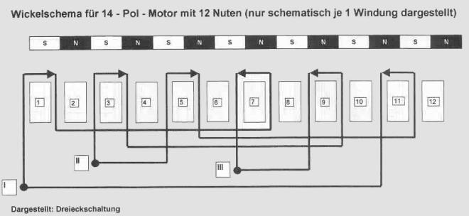
Winding schematic
A schematic drawing of the winding is shown below. Other picture could be found here. Each wire coil is connected in series with the one directly opposite, this one is wound the other way round (to get one magnetic south and one magnetic north). The interconnecting wires must not be to tight, they must not interfere with the end disks of motor and the rotor. For motors designed for very low voltages, it is also possible to connect the coils in parallel but watch the direction of the current flow. Instead of the triangle connection of the three coil groups shown below it is also possible to use a star connection. That lowers the RPM/volt by a factor of 1.73.
And now it is time to put everything together
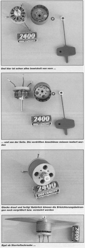 |
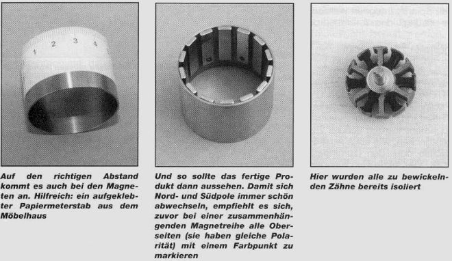
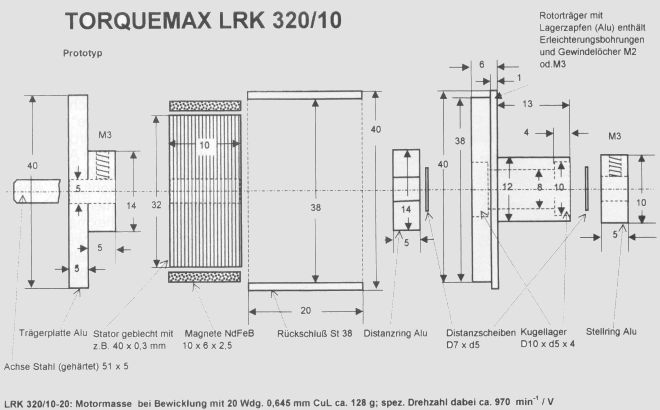
In Principe the joining of the components is given by the drawing. At first the ready wound stator plus the aluminium distance ring is glued well to the 5 millimetre steel shaft. The rear mounting disk is held by a set screw and can be taken off again. The glueing of the magnets to the soft iron feedback ring is done with cyano glue, or more comfortable with Locktite 326 glue and Activator 7649. Note that the magnets only touch the iron ring with the edges. It is important to maintain the same distance between the pieces and also line them up axially. One can use a paper measuring band around the circumference of the rotor. Use a 90° jig from pliable plastic to line the magnets up. One end of the magnets should be in line with one end of the iron ring. NdFeB-magnets with a width of 5 to 6 millimetres and thickness of 2 to 2.5 millimetres are a good choice. The thickness depends on the diameter of the iron feed back ring and the aluminium rotor end disk. The design is made for a 0.5 millimetre air split. This distance must not be smaller. If one uses 6 millimetre magnets it wouldn't hurt to increase the air split on both sides with another 0.1 to 0.2 millimetre. You lose some torque but the iron losses (by increasing rpm) can be a lot lower. If the desireded magnet length isn't available, smaller pieces can be added in a row. It is even possible to cut magnets but that kind of job isn't much fun The iron feed back ring and the rotor disk are glued like the magnets. The ball bearings do not have to be glued if the aluminium disk is machined to exact dimensions to allow them to be pressed in. In this way, they are easier to change. |
Blue drawings:
Where to get these parts
In the prototypes a larger ball bearing was used, 10 mm x 5 mm x 4 mm (Kyosho Nr. 1901). The propeller hole had to be enlarged to 12 millimetre diameter and props drilled to match. Later narrow ring ball bearings, 8 mm x 5 mm x 2.5 mm (Kyosho Nr. 1902) were used. Now the propellor hole could be reduced to 10 millimetre and propellers also drilled 10 millimetre. Another advantage: commercial centre pieces for folding props with a width of 12 mm and with 8 mm holes can be drilled to fit. In the normal case, the propeller sits in the middle of the two ball bearings and a possible out-of-balance situation does not matter much. The distance disks can also be had from the Kyosho program (Nr. 96643).
It can sometimes be difficult to buy magnets in the small numbers one needs. The suppliers might need to be persuaded. If nothing else helps, the author (Ludwig Retzbach) can supply magnets in the sizes 12 mm x 5.9 mm x 2 mm and 24 mm x 5.9 mm x 2 mm and also metal stator disks in 32 and 35.5 millimetre diameter. Address thru the Neckar-Verlag publishing house.
(Some German suppliers are also listed in the original elektroModell article)
IBS Magnet
Kurfürstenstr. 92
D-12105 Berlin
http://www.ibsmagnet.de
Vacuumschmelze
Postfach
D-63412 Hanau
Magnetfabrik Schram berg
Max-Plank-Str. 15
D- 78713 Schramberg-Sulgen
Tridelta Magnetsysteme GmbH
Ostkirchenstr. 177
D-44287 Dortmund
Some information from Peter Rother (translator of this article and LRK fan):
there is a lot of information, drawings, calculation, measurements on my LRK page