Excerpt from elektroModell 1/2001, converted to HTML by Peter Rother, August 2001
Motor Fever
 |
Wow! Ludwig Retzbach's article about his DIY motor has hit me like a bomb. An eager builder of electric motors, I was hooked. Although I have constructed several motors already, both with mechanical and with, some very fancy, opto-electronic commutators, I had never seen this concept before from a standpoint of materials used and required precision. |
First step in the preparations was the tuning of my lathe: this is an own construction of my grand-grandfather, a proud 80 (!!) years old, which has become very sloppy over the years. To even out the forces excerted when the longitudinal carriage is operated by hand I fitted gears to a stepper motor (Conrad, DM 5.-) driven by appropriate electronics to give a continuous feed as well as fast forward in both directions.The effect was even more astonishing than as hoped for: the wobbly and grooved surface of before had given way to a first class shiny surface! Even turning of inside surfaces in steel (for the fluxring), unthinkable up to now, was possible with good results. Next was the aquisition of a rigid aluminium alloy (AIMgSi1), since I planned on a strongly reduced driveshaft diameter and because this material does not flow as much. Notwithstanding that I strongly recommend the use of copious amounts of methylated spirits as lubrication. The result will be more accurate and shiny.
Following
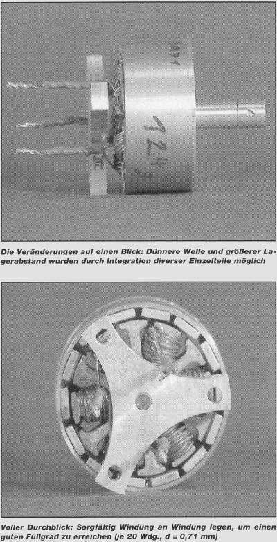
significant changes were made
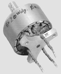
I used stator plates with an outer diameter of 34,7 mm and an inner diameter of 6 mm (thanks to mr. Lehner for making these available without ado at a very economic price) and magnets of 10 mm x 7 mm x 2 mm dimensions (standard size,however it does get a bit cramped in spite of the larger diameter). 20 Windings at d = 0,71 mm were applied.
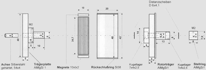
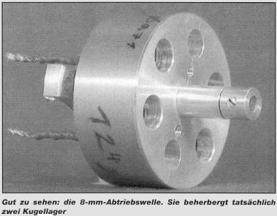
Instead of the 5 mm shaft a 4 mm hardened and straightened silversteel shaft was used. The forward aluminium spacer and the rotor carrier were integrated into one piece to increase the between bearings distance and thus decrease the leverage. Also, mini-ballbearings of only 7 mm x 4 mm x 2,5 mm (0 x d x B) were used. With these, and by carefully turning out the bearing seats it became possible to realize a driveshaft diameter of only 8 mm. This avoids the need to enlarge the propellor hole completely, so it remains fit for use on other propulsions.
|
|
The rear bearer plate was integrated into one piece with the required 4/6mm bushing for the stator plates, thus supporting the rearward part of the shaft which is particular susceptable to bending. This was drilled with a 3,95 mm drill (from a reamer set), withdrawing regularly with ample application of meths to remove the cuttings, resulting in a tight fit of the 4 mm shaft. The piece was given an elegant shape with a rotary cutter, thereby saving some weight as well. The stepper motor mentioned above was worth its weight in gold: "only" throwing the direction switch 500 times rather than an equal number of times a series of steady turns on the feeder crank. Since the forward grubscrews do not have a lot of meat for the threads two indentations were grounded into the shaft with a mini cutter. After a thorough degreaseing everything was assembled with Loctite (cover the shaft and bearings lightly as well). To glue the magnets simply and accurately a 14 legged star was drawn and stuck to a steel plate with kitchen wrap. Everything will hold itself in place and the magnets will be aligned automatically - add cyano and you are ready. |
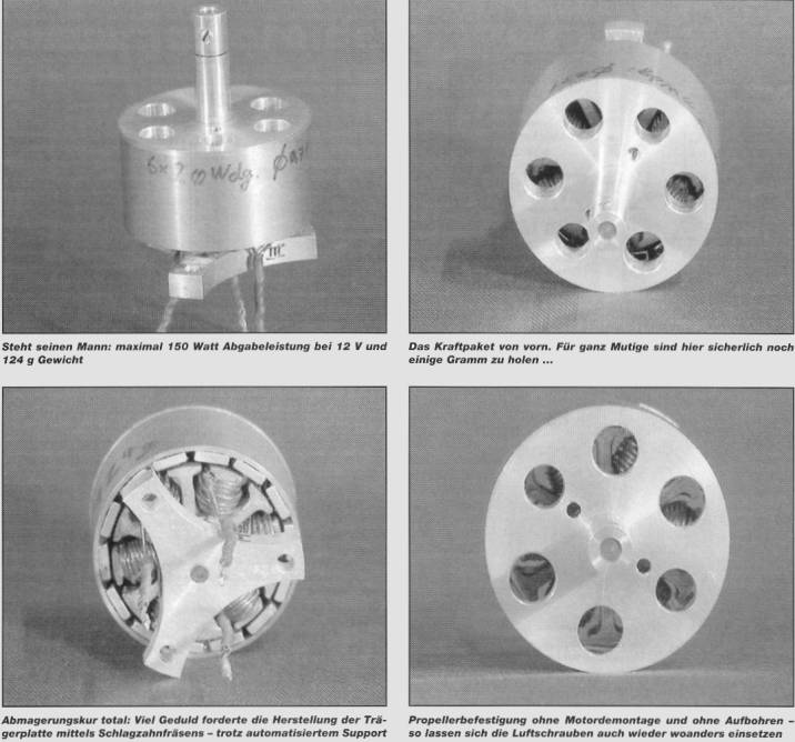
The completed motor
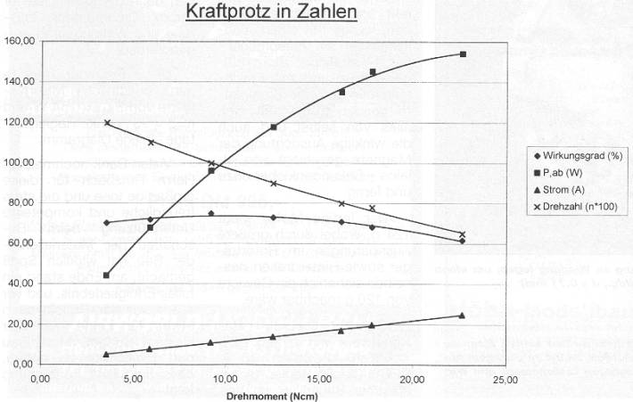
The completed motor weighs 124 g, but with larger openings in the rotor carrier and cutting out a void in the back of same this could have been reduced to approx. 120 g. The work of art was tested with a JETI 40-3P (6-12 cells, 40 A, BEC). This ESC made in the Czech Republic is very cheap (DM 170.-) when compared to our local products and yet reliable. Only at abrupt load variations and when overloaded it will show some hickups. The graphs for current, torque, power and efficiency were recorded with the aid of a car battery, current and voltage meters and a digital scale. This procedure yielded very remarkable maximum values of Pmax = 154 W and etamax = 75% (incl. ESC) - see the diagram below.
Again many thanks to Mr. Retzbach for
the great idea and the always competent and friendly assistance
in the aquisition of materials - the construction was really
enjoyable and resulted in a great succes and above all it was
a project for people with a modest budget. Pure modelling! I
can only hope for a follow up soon...
Note of the editor
Motors with ca. 40 mm rotor diameter shall be fitted with magnets
of 6 mm. maximum width, since torque and efficiency will suffer
if the magnets are too close together.
the HTML- page builder has made a LRK350-20 for himself, this time with a rotating shaft, and is thrilled with the running qualities of the motor.