Pictures from the Workshop
translation by Max Zuijdendorp
Many pictures are also used on other pages. Some pictures
show earlier versions of the motor.We have already some development
behind us so the current design of the LRK350-20 (20 mm Stator) and the
LRK350-12
(12 mm Stator) represents pretty much the optimum and withstood
the rough day to day flying for weeks in all kinds of weather.
The design of the Turned
parts is robust as a result of this (no aluminium where
steel is needed, for instance where threaded connections are
used).
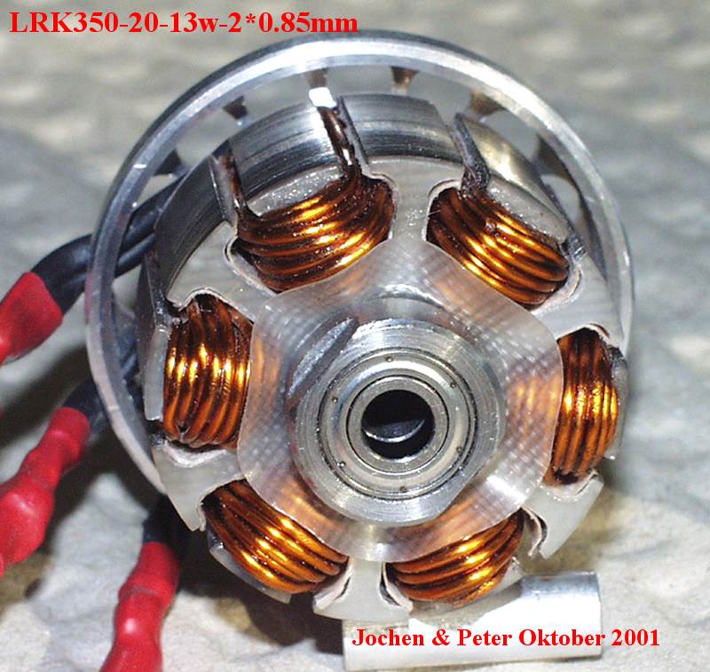
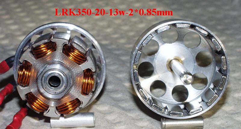
Here is a close picture of the latest creation of the LRK350-20-13w-2*0.85mm.
It is intended for 12 cells and 600 W. the equivalent wire diameter
is 1.2 mm and the motor
internal resistance only 0.018 Ohm.
With that the motor turns a 16"x10" Aeronaut without
gear (like most LRKs).
Earlier we did not pack the windings as tight, but the measurements
were mercyless! Since the idle current is very low, also when
partly loaded, as proven by the Measurements at part load, the copper
losses remain our main enemy and will get our very special attention.
The result is shining: up to 91% Motor
efficiency (LRK350-20 at 150 W).
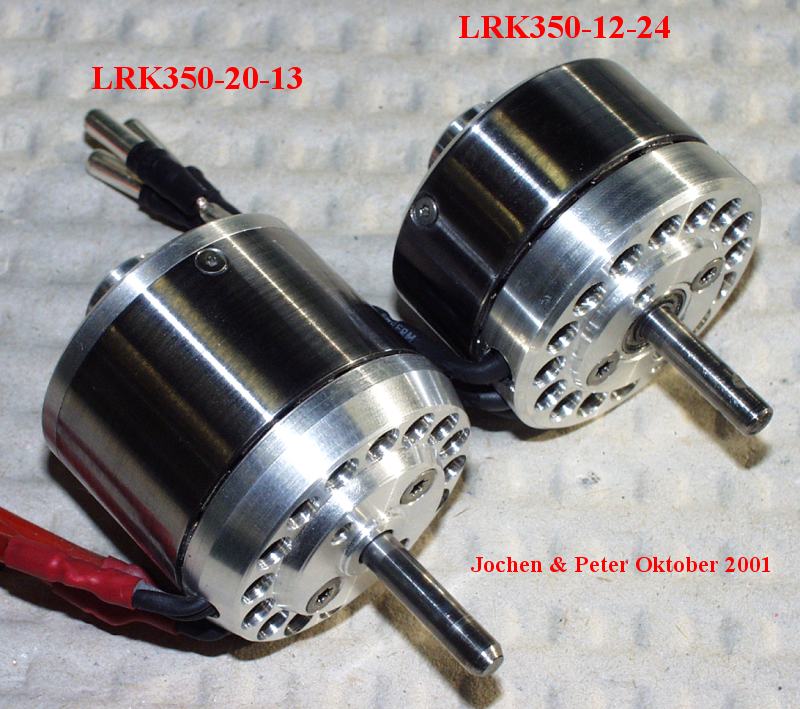
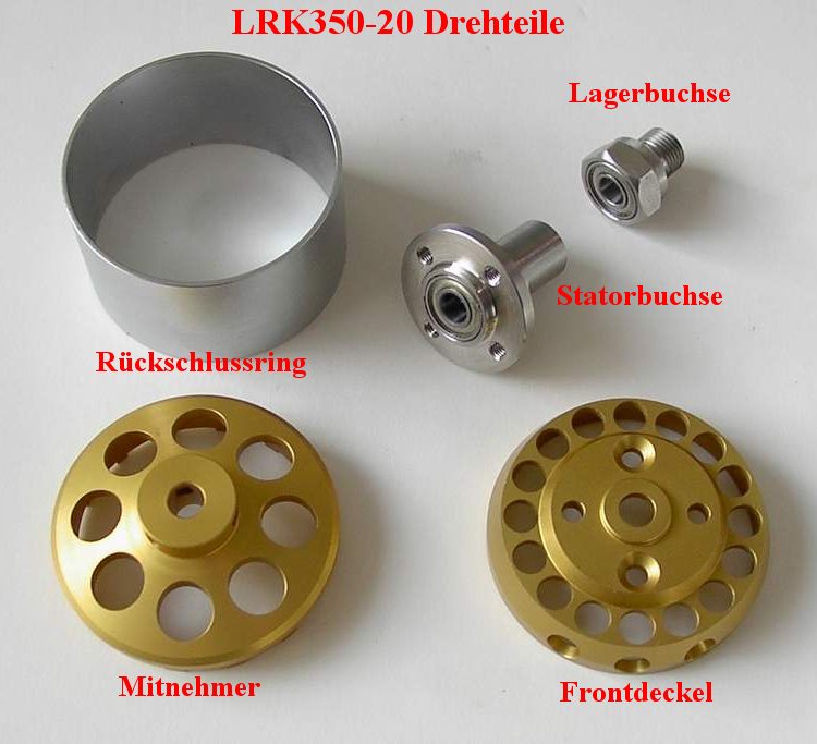
Assembled, the two newborns look like this:
The belonging Set
of turned parts does not have to be hidden either. To
be clear: the roller bearing housings / stator carrier and the
rotor bell are made from steel, not aluminium, which in my opinion
guarantees a long service life (creep behaviour of aluminium).
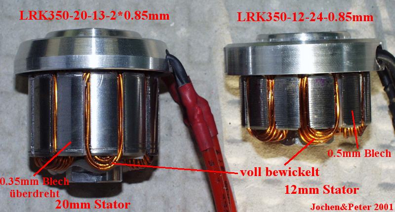
If you have already had to wind a stator
coil very tightly you will value the separate screwed stator,
independent from the front cover. It is nearly impossible to
draw the wire through the slots while holding the stator assembly
in your hand. With the screwed assembly as shown, you can immobilize
it in a vice and pull the wire through forcefully (several kilogram-force).
If you do not have this srewed construction, you will be wondering
how to hold the stator after only two coils have been wound,
because you cannot grip it in the vice with the exposed windings.
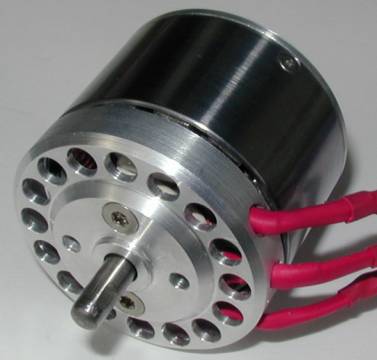
After completion of the assembly the motor looks like this
when the two main parts are separated :
We have also gone through a stage of development where the
propellor adapter was integrated in the rotor bell:
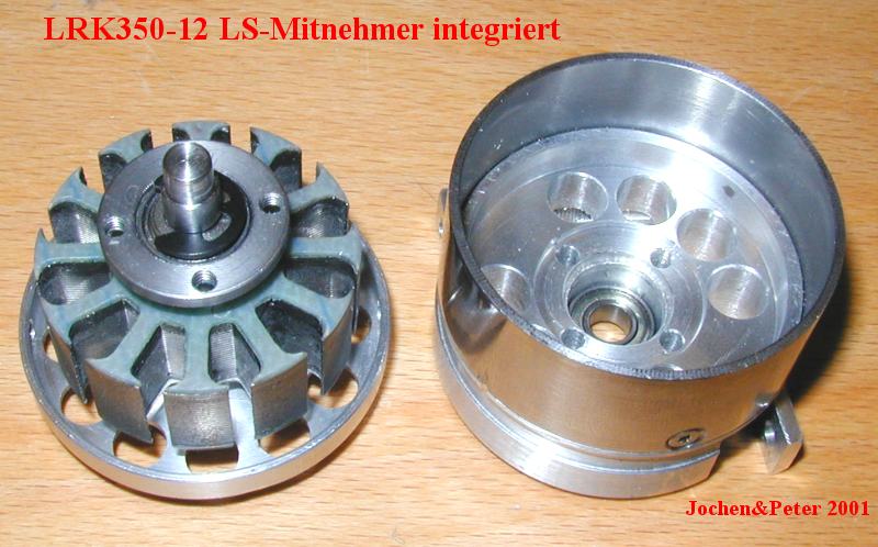
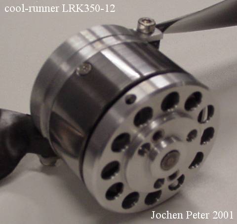
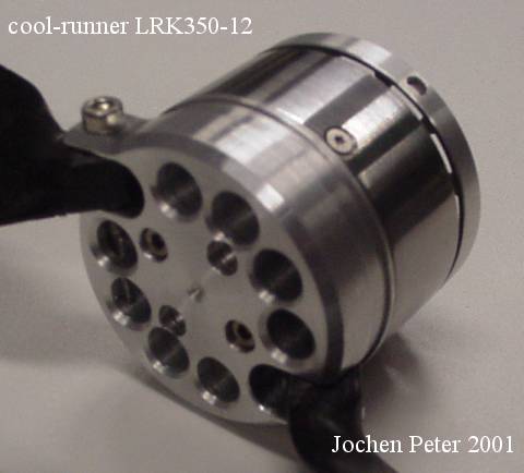 The assembled motor, a LRK350-12
looks very nice, but the invested effort is too high. The assembled motor, a LRK350-12
looks very nice, but the invested effort is too high.
Why we named the motor "Cool Runner"?
Because it was fixed at the very front of the fuselage it
received first class cooling.
It was a sidestep. We did leave the desire for an "inside
fuselage" motor for once!!
To close out, here are two wellknown faces:
LRK350-20-13 and LRK350-20-11
back
to the LRK main site |