|
 |
This is the second SPEEDY, which powerfully lifted the heavy ASW24 with the LRK350-20-13 in the air some days ago. Because it was very windy we did not use the DataLogger for measurements. The Telario-Talk altitude indications did show 20% more climb than with the Ultra 1300-10, in the same runtime! The altitude graphs will follow as soon as we have a dead calm period. |
I do not want to discourage anybody, but for the first excursion into SMD assembly you should look for something else. For those who have already experience with a project I would like to give some tips. You will need as a minimum (because of the narrow spacing of the pc-board tracks):
Then you should abide by the very well done step-by-step instructions. It is not only important that your soldering is sound but also that the 15 V generated in the circuit does not get to your processor via some unintended track bridge and destroys it. It also pays to strike the components that you have placed from your component list. Most resistors are type 0805, securely packed in bags.
Despite all that I used a full eleven hours to build the first SPEEDY-BL, although I am pretty experienced in this type of work, and had planned on only 4-5 hours. Most of that time I used to understand what the processor does. And why the motor only stuttered in spite of the EMK position signals arriving in good order when the motor was turned by hand.
Conclusion:
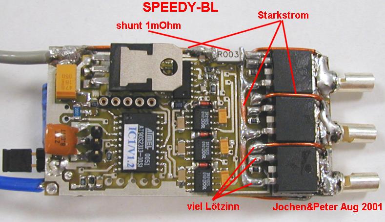
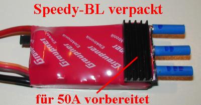
Without oscilloscope you have no hope of not cursing your work. With one you will proceed without too much difficulty. To give the builder a little bit of a headstart I have generated some pictures on my works scope (Agilent Infenion 1GHz) , to show the functioning principle of the controller. With the knowledge on how the controller should function I built the second SPEEDY, without following the instructions (all components soldered at once, don't do it!), within only 3 hours, ready and tested (see above wrapped and detailed here).
Controller functioning at full load
This is the block diagram as it can be seen on Jo's homepage:
When the motor turns, it will generate 3 position signals, so-called EMK signals.They tell the processor ("Motor-Steuerung" in the diagram) what the position of the rotor is. On the scope screen picture this is the lower, purple, curve.
The phases A, B, C supply the BL motor with the battery voltage, with a 120 deg. offset, like it should be with a 3-phase controller. That looks like this: (click on the picture to zoom in if you want)
To connect phase A to ground you have to put 15 V to the gate of the lower MOSFET (there are 6 MOSFET's in the 3 phase H-bridge)(yellow line, "Gate A"):
To get such nice 3-phase voltages the MOSFET gate inputs look like this (click on it to zoom in temporarily):
That was simple enough, was'nt it? Now for something a little bit more complicated ...
Controller functional principle during start and part load
To start the motor you cannot simply bang the full voltage on the terminals, your windings will burn through in no time. The controller has to offer very low power very carefully and check the EMK signals to see if its partner wants to play ball. Only when the position (EMK) signals follow the direction of the rotation of the forced-on magnetic field this can be accelerated, the load increased and finally brought to full load. This is why part load ability is a very important and difficult mission for the controller (and its developer). The Speedy-BL also provides idling when under part load, which reduces heat up of the controller dramatically. We will not discuss this here to avoid distraction from the main line-of-thought.
(Many commercial controllers heat up in such a way that you cannot touch the controller after being connected to my LRK350-20-15 for 5 seconds when working under part load conditions. The SPEEDY remains "cool")
Let's go back to part load:
Because the BL motor under part load should draw less current combined with the same voltage, we have to chop the nice square input blocks going to the MOSFETs (see above), to lower the average current through each phase. It will look like this (click to zoom in):
With this chopping the BL motor will get what it needs, a chopped voltage following the trapeziodal curves as before:
Why the EMK signals are not chopped despite being derived from phases A, B and C will remain a sweet secret of the developer ( and mine also). The processor (and thus the motor driver) would be pretty confused when it would get the chopped position signals.
I hope that the brave builders of this circuit know now which signals can be expected where. And realize that the processor must be a pretty smart cookie to keep pace in this chaos of signals, at field rpm exceeding 50.000.
And this is me, with the Speedy-BL:
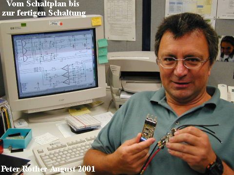 |
Peter works for Agilent Technologies. For almost 20 years he has developed instruments for medical and chemical analysis, space exploration and lately for optical internet communication.He has done work for the Max-Planck institute, NASA (Jupiter probe "Galileo"), Hewlett-Packard Labs in California etc. Peter is at his best when there is something to be measured, to be calculated or to be developed, that is if he hasn't caught another giant thermal at the flying field. Extended bicycle tours (100km) are as much a part of his hobbies as measuring a LRK or surfing in rconline . |