Excerpt from ElektroModell 4/2001,
original HTML by Peter Rother, translation into English by Max Zuijdendorp, Nov. 2001
Performance Measurements
on Electric Motors
 |
Which electric motor to choose? In the brochure they are all the very best. The buyer has the torture of making the choice: Super-Speed-Pro, turns a 10x6 Hyperprop at 7900 rpm, drawing 19 amps, or the Giga-power-pro, which does 8200 rpm but consumes 3 amps more? What do claims like "best efficiency in all power ranges" mean in practical use? |
Yes, if you only could verify these claims in a simple way.
That will give certainty, but also the danger that many up to
then interesting discussions will have an abrupt end. Now then,
what about a lie detector for strong stories and fast salesman
talk, your own test rig for electric motors?
Motor test rig! Does'nt that sound like mega$$ and endless effort?
Have no fear, this is not a HighTech orgy! You can produce this
with instruments that are usually available in the modellers
workshop, like multimeter, optical tachometer and electronic
scale, and a little craftwork, also on a low budget. The rig
itself is constructed from metal, reinforced epoxy sheet or multilayered
plywood,depending on what your skills are or what has accumulated
over the years in your shop. Accuracy is the main ingredient.
Neither do you have to craft electronics nor add new interfaces
to your home PC. If you have one, it will be easier to calculate
the results of your measurements using a spreadsheet program
such as MS-Excel, but a pocket calculator will suffice. The physics
of performance calculations are comparatively simple, so you
can compare your results with the published results from the
various motor manufacturers with sufficient accuracy. And when
the effiency values as measured on your DIY rig sometimes are
a few points below the published figures it does not mean that
the following instructions for the conctruction of it have basic
errors.
Every motor can deliver any torque, if you send enough Amps through it. Speed is not a problem either. But the mark of quality for an electric motor is its efficiency. Not only the peak value that stands out, but the general level achieved in the targeted operating envelope. Efficiency is represented by the Greek character Eta. It is calculated as the relation of the delivered mechanical shaft power (P_out or P_mech) to the invested electrical power (P_in or P_el).
Recording the electrical values is the easiest, although often underestimated, part. As you probably know, electrical power is calculated as the product of Voltage (U, also known as potential), and Current (I).
To rule out corruption of the measured values because of Voltage drop in the connecting cables (we are only interested in the performance of the motor), you have to measure Voltage as close as possible to the motor, or ESC in case of a brushless motor. Following trick helps you with that: solder dressmakers pins to the leads of the Voltmeter, and push these through the power cable insulation close to the measured object. Voltage measurement takes almost zero current, so you can use thin pins and leads. A common multimeter will suffice, preferrably with a data hold button to relieve the limited data recording capability of you own brain.
To measure current is a little bit more complex, because you will need a shunt resistor in the circuit. Manufacturers of ESC's do have reasons to warn you for these "devil's devices", because you can overload the input condenser. That is why a support condenser of 220 to 470 uF/63 V must be inserted between shunt and ESC (see diagram). If you use a 1 mOhm shunt however, as proposed here, the circuit will practically not be affected. This way, a common multimeter with a range setting of 200 mV can be used to measure currents up to 199,9 A. That must be sufficient, both in range and sensitivity (100 mA). If your interest lies with low powered motors, a 10 mOhm shunt will bring a 10 times higher sensitivity.
The accuracy of this kind of setup fulfills the requirements of "advanced household use", as long as the current flows nearly continuous. This is the case for any motor when measured at "full throttle". The circuit as described is not very suitable for "chopped" operation, because that will result in a so-called "blind" current on top of the active current. Unfortunately, the Amp meter does not know the difference and measures both, or rather the sum of them. The voltage is likely to become rippled at the same time, so we are comparing apparent electrical input power with real mechanical output power, which does not really flatter the motor being tested. Be suspicious about the clamp-type Ampmeters offered for hobby use, we are discussing "measuring" after all!
Physically the mechanical power is the product of the Torque moment (M) and angular velocity (Omega). The latter has a direct relation to the speed of rotation in rpm n (n=Omega*2*PI/60) which is therefore used as measured entity.
M is measured in Newtonmeter (Nm), n in rpm (min-1). As every model pilot knows, rpm is measured easily with opto-electronics, provided that the rotating part suitably reflects light intermittently. Pulsing light sources like lightbulbs (on AC) and in particular TL-tubes can be a mighty interference. At first the author brightened up his test rig with a 12 V car fog light. In the meantime I have mustered a laser tach, with the added bonus of a 5 digit resolution. Infrared tachs with their own lightsource are also known to be resistent to room lighting interference. Often these "upper class" instruments will also have a stress reducing memory function.
And so we have come to the last, and real problem: measuring the torque moment. Torque, as you will remember, is force times leverage arm. The latter can be established with a tapemeasure, and because it is a fixed value, we can bracket and set it. Further, we require a scale with adequate accuracy, a job well suited for our letter-scale. In stead of matter to be weighed we will load the scale with the above mentioned leverage arm. But all things in order! Merits to you if you can find letter-scale with data hold function and within a hobby budget. Normally a range up to 2000 grams is OK, but if you want to restrict yourself to motors in the lower power class (up to 250 W), you will measure more accurately with a 200 grams range.
At this point two more questions come up: how do you persuade an electric motor to gradually built up torque and with that force and where would you measure it?
 Well, force can only come into
effect where resistance can be expected. Ergo you have to be
able to brake the motor. Th simplest way is to fit a propellor
of suitable dimensions. That will kill two birds with one stone:
the motor shows its potential and at the same time the propellor
size recommendation. Theoretically ideal, in practice flawed.
The suitability of your hobby workshop as a part-time wind tunnel
is often very questionable. And even when your models are lashed
to their shelves and you and your assistants are wearing full
gale weather gear, the cursed invisible draft that loads or unloads
your scale and corrupts your results remains. In any case this
author has the experience that it takes a lot to shield the approx.
1 dm large scale plateau effectively enough to avoid errors of
several milliNewtons caused by the whirling airstream in its
immediate vicinity, degrading the well-intended measurement to
an approximation. Now and then I have also witnessed that, dependent
from the room dimensions, the circular flow created a kind of
feedback and influenced the propellor rpm. Sometimes even increasing
oscillations occurred. With all that repeatibility of the results
cannot be expected. It should also be remembered that the absorbed
power of a propellor varies with varying atmospheric pressure
and humidity to a degree that cannot be ignored. For safety reasons
the propellor should also be protected with a cage or protective
ring. In short, I can hardly recommend this type of brake for
your motor!
Well, force can only come into
effect where resistance can be expected. Ergo you have to be
able to brake the motor. Th simplest way is to fit a propellor
of suitable dimensions. That will kill two birds with one stone:
the motor shows its potential and at the same time the propellor
size recommendation. Theoretically ideal, in practice flawed.
The suitability of your hobby workshop as a part-time wind tunnel
is often very questionable. And even when your models are lashed
to their shelves and you and your assistants are wearing full
gale weather gear, the cursed invisible draft that loads or unloads
your scale and corrupts your results remains. In any case this
author has the experience that it takes a lot to shield the approx.
1 dm large scale plateau effectively enough to avoid errors of
several milliNewtons caused by the whirling airstream in its
immediate vicinity, degrading the well-intended measurement to
an approximation. Now and then I have also witnessed that, dependent
from the room dimensions, the circular flow created a kind of
feedback and influenced the propellor rpm. Sometimes even increasing
oscillations occurred. With all that repeatibility of the results
cannot be expected. It should also be remembered that the absorbed
power of a propellor varies with varying atmospheric pressure
and humidity to a degree that cannot be ignored. For safety reasons
the propellor should also be protected with a cage or protective
ring. In short, I can hardly recommend this type of brake for
your motor!
A better solution, which is also favoured in the laboratory, is the brake-generator. Here the test motor drives a second one, working as a generator which can be loaded with a variable resistance. Reassign a large as possible motor from your hobby collection for this purpose. Getting the required heavy duty resistors for the load is not very prob;ematic, but with the power ranges of todays motors they should be able to endure some torture. Car headlight bulbs connected in series or parallel is a proven arrangement, but even better is a simple constant current drain, as described by the author in his book "Batteries & Chargers" (in German, Neckar Verlag, ISBN 3-7883-2142-3, 12. Auflage, S. 106). This has the advantage of operating independent of the rpm.
But here also the devil hides in the detail. Because both motor and generator have to be supported free to rotate (I will tell you why later), the coupling of the shafts is not without problems. Maybe you can get away with elastomere couplings like they are used in ships propulsions. But also with those I experienced time and again these cursed increasing oscillations, which do not much for the accuracy of the measurements. Important is that both shafts are lined up very carefully.
Unsuitable for the function of load generator are unfortunately all those motors with a strong, permanent pole attraction (like the old Keller motors which are otherwise great candidates because of their robust construction). Because of their pull-away moment you will get an unpredictable starting offset, exceeding every acceptable tolerance for error. I found the older ASTRO and Bühler ferrite motors to be best suitable for the purpose, since these are motors with multi-pole rotors, oblique slots and segment or ring type magnets and thus with a minimal pull-away moment (they can also be found in older car fan motors. Especially ideal for these applications would be the heavy duty bell rotor motors (Kontronk-Tango) or the rotating field motors with ironless coils, as manufactured by the Lehner and Hacker companies. But let's not get carried away, you can see an increasing number of problems, each of which can be overcome, but which also lead us to investigate a third solution, the Eddy-current brake.
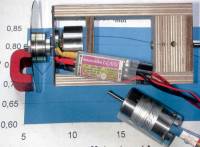
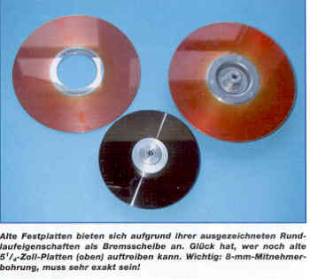 The principle and realization
of the Eddy-current brake with "household means" is
relatively simple: you take a very round aluminium or copper
disk, drill a very centric 8 mm hole in it to fit it on a commercial
prop driver (preferrably with conical clamp) and spin it in a
magnetic field. If you, in your quest to stop the dive of the
stockmarket, have decided to scrap your old PC and buy a new
one, you have already found the solution. Even if the computer
bugs have eaten your harddisk or if you have entered: "format
C:", it will still retain precisely the qualities for the
application mentioned above: perfectly balanced rotation and
high rpm ability. You only have to prise it off gently and enlarge
the central hole accordingly (on a lathe!).
The principle and realization
of the Eddy-current brake with "household means" is
relatively simple: you take a very round aluminium or copper
disk, drill a very centric 8 mm hole in it to fit it on a commercial
prop driver (preferrably with conical clamp) and spin it in a
magnetic field. If you, in your quest to stop the dive of the
stockmarket, have decided to scrap your old PC and buy a new
one, you have already found the solution. Even if the computer
bugs have eaten your harddisk or if you have entered: "format
C:", it will still retain precisely the qualities for the
application mentioned above: perfectly balanced rotation and
high rpm ability. You only have to prise it off gently and enlarge
the central hole accordingly (on a lathe!).
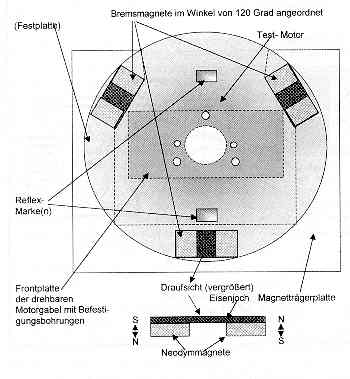
Braking the slippery round thingy is achieved with a magnetic field (which will also ensure total erasion of your data). In professional installations this is often generated with strong electric coils, fed with current from a variable transformer. The stronger the field, the sronger the braking effect. Since modern neodym blocks can deliver a similar field without an external supply of energy, they are a better choice. We only have to vary the distance of the permanent magnets to the disks to vary the braking action. At first I enrolled the assistance of a 150-N/cm powerservo, with apparent success. But the loads became excessive when braking strongly, with the magnets close to the rotating disk (the magnets are repulsed violently).
A better solution is a spindle drive, mainly thanks to its self stemming ability. A M6 thread spindle, turned by a small geared motor moves the magnet carrier back and forth at the push of a button (or you can turn it manually with a crank).
The carrier must be guided with sufficiently close tolerances, to stop all signs of vibration. If the magnets approach the disk from behind, the motor bearings will see an axial force as if it was a tractor propellor. To avoid an assymmetric force you should fit 2 magnet assemblies minimum, better still three, equally spaced at 180 respectively 120 degrees around the circumference of the disk (see sketch). Each magnet assembly consists of an iron plate ("Eisenjoch" in German) with two neodym magnets attached, oriented as shown in the sketch.
 A small part of
the power will be "burned" by the drag of the rotating
disk, which will set the minimum braking torque value (dependent
on rpm). Electrically, the aluminium disk functions as an internally
short-circuited generator. The short circuit current causes the
braking torque. Its value increases with increased magnetic field,
which in turn grows with diminishing air gap; but more than proportionally.
Therefore the gap should be adjusted finely in the highest range
of the braking torque, thus requiring a large gear ratio on the
spindle drive.
A small part of
the power will be "burned" by the drag of the rotating
disk, which will set the minimum braking torque value (dependent
on rpm). Electrically, the aluminium disk functions as an internally
short-circuited generator. The short circuit current causes the
braking torque. Its value increases with increased magnetic field,
which in turn grows with diminishing air gap; but more than proportionally.
Therefore the gap should be adjusted finely in the highest range
of the braking torque, thus requiring a large gear ratio on the
spindle drive.
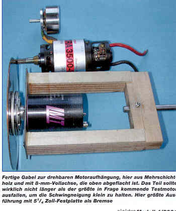
The disk will heat up quickly (after all it will convert 60 to 90 % of the energy fed to the motor into heat), and it is nice that the fast rotation improves its cooling. However, small disks do need a cooldown period after a prolonged series of measurements. In principle you could mount the magnet carrier in bearings and use it to measure the torque, but this would not take the rpm dependent drag moment into account. Therefore it is better to mount the test motor in such a way that it can rotate freely, and measure the countering torque (action=reaction).
This is exactly the point where you must consider your design carefully, to avoid introducing systematic or accidental errors: the countering torque causing the motor housing to rotate against the direction of the shaft rotation, has to find its way to the weighing scale plateau with as little disturbance as possible, i.e. it should not "fade" along the way. Therefore it is important that the motor shaft and the motor carrier support axis are carefully aligned, and that the bearing resistance is reduced to the minimum. Submerge the rollerbearings several days in aceton before fitting, spinning them firmly at intervals to remove the high viscosity bearing grease. Replace it with thin sewingmachine oil.
Another cause of corrupting forces are the power cables. Guide them close to the axis, at best through a hollow shaft. Several thin cables (e.g. 2 to 3 x 1,5 mm2) are better than one thick cable (e.g. 1 x 2,5 to 4,0 mm2). Guide the voltage measurement cables (those with the sewing pins) in parallel, and include a servo extension lead for measurements including an ESC or a brushless controller.
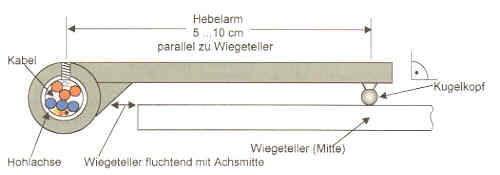
When the arm length is defined a given torque creates a defined force on the weighing plataeu (as close to the middle as possible). In principle the length of the arm can be freely chosen. The shorter it is however, the larger the force on the scale and with that the resolution of it. But the arm should not be made shorter than 50 mm. The force is transmitted from the arm to the scale with a ball head. To dampen the vibration it is advisable to lay a thin felt piece between head and weighing plateau. The arm can rest on the scale with 10 - 20 grams preload, zero adjustment is a mandatory preparation for each measurement anyway. Note that the top of the weighing plateau shall be level with the support axis.
Lastly we have to revive some basic physics. Since weighing scales of the species described above directly register the excerted force, but on this continent are calibrated in grams (g), they will indicate 100 exactly when loaded with a bar of chocolate with a mass of 0,100 kg. According to the law of gravitation this is only 0,981 N if the gravitational acceleration is 9,81 m/sec2. Keen as we are on optimum accuracy of our measurements we want to avoid being tripped by Sir Isaac Newton and have to correct our readings with the appropriate factor, which is simply done in the calculation program itself (see below).
It is advisable to reach agreement with your inner lazy self (which will always go for the easy solution) if you only want a nice set of results or meaningful measurements. If you opt for nice, it suffices to measure on a cold motor. For meaningful you should allow the motor to reach operating temperature. In any case all readings should be taken at approximately the same temperature. It is good practice to define a temperature measuring point inside the motor which should read 60 °C at least. You could also consider to do all measuring with a speed governor. Only then will comparisons between brushed and brushless motors make sense.
If you use batteries, you will have to live with a voltage which depends on current draw and discharge status. A better proposal is a mains power supply, with which you should aim to keep the voltage constant during a series of measurements. The author prefers to change the current as an independent variable, e.g. in steps of 5 A, and record the values of rpm and torque moment at every step.
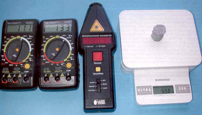
Very important: all 4 variables must be recorded simultaneaously. To do that, the data hold buttons of voltage, current and rpm meters must be pushed as one. The weighing scale reading has to be stored in the human memory at the same time (at least with my setup for now). Don't forget to set it to zero before each reading!. You can also make life easy by using a digital camera to take a snapshot of all readings together.
It is best to migrate the results into your PC right away, or write them in a previously prepared list looking something like this:
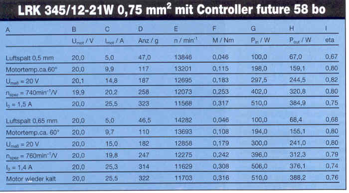
In the above table the results are shown of measurements on two identical LRK motors (see elektroModell 2/2001), except for the air gap ("Luftspalt" in German), in order to establish the effect of enlarging this gap. The bottom line shows the results of measuring a cold motor. The use of MS-Excel is very helpful here, which automatically calculates the data from the entries in columns B through E.
As you can see in column D the scale readings are entered simply in grams. The calculated torque moment value can be found in column F, where Newton's constant 9,81 m/s2 and the arm length (in this case 100 mm=0,1 m) are incorporated according to the formula (grams are converted to kilograms):
On the first line you can see that a recorded 47 g calculates as 0,046 Nm. The input power (column G) is the product of B x C and results in exactly 100 Watts for this line.
The output power (column H) is calculated from E x F x 0,1047 and calculates as 67 Watt in this example. With that the efficiency eta is established as division H/G = 0,67 (67%). This comparatively low value of eta is the result of "underpowering" the LRK motor at only 5 A. In this power range you will see a domination of the iron core losses. That also explains the slightly better result at increased air gap. Obviously the eta in the power range for which the motor was intended is of more interest.
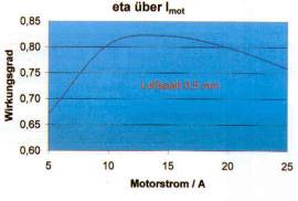 It turns out that between 10 and 20 A an
eta of over 80% is achieved. This is therefore the preferred
operating range of the tested motor. If you accept a minimum
eta of 75% you are able to convert more than 500 W with a motor
of this type of construction. With that everything important
has been explained about our test rig. I admit it, many glossy
brochures have more exciting stuff to read!
It turns out that between 10 and 20 A an
eta of over 80% is achieved. This is therefore the preferred
operating range of the tested motor. If you accept a minimum
eta of 75% you are able to convert more than 500 W with a motor
of this type of construction. With that everything important
has been explained about our test rig. I admit it, many glossy
brochures have more exciting stuff to read!