|
|||
Nowadays we're confronted with radio waves all the time.Many of us use mobile phones without ever thinking about the complex processes and high technology making this possible. We do not need to. Nobody will get hurt when the link is temporarily broken. Not so in model flying.We often move large models at high speed in close proximity of human beings.If we want to minimize the possibility of an accident, we need to understand the way our commands are transferred to the model and then optimize this for our specific application.The whole command sequence, from the pilot's hand to the control surface in the model , is made up out of different parts that we are able to control perfectly these days: scanning of the stick position in the transmitter, mixing with other commands, generating and broadcasting of the radio signal, and at the end of the chain the moving of the control surface by means of the servo. From transmitter to receiverUnfortunately, the path between the transmitter and the receiver is disturbed by many influences. Among these are internal influences like sparking in the electric motor, bad antenna routing, or outside influences like general High Frequency pollution of our environment by permanent but unknown sources, television and radio broadcasting or mobile communication.I do not wish to talk about somebody using the same frequency. On the other hand we have the controlling task, quite different for a slow rudder-elevator glider, perfectly capable to float around by itself for a while, compared to an agile helicopter, crashing instantly (because of its inherent instability) when control is temporarely lost. The frame rate of the RC commands is, due to the safety requirements, directly related to the accuracy of the servo movement following commands, still acceptable connection losses and the possibility to report glitches to the pilot, so he can land early while this is still possible. FM – transmitter for PPM and PCM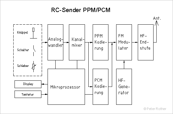 Usually,as opposed to PCM, PPM equipment is referred to as FM. This could lead to the belief that PCM is not FM. This is wrong! PPM and PCM use the same Frequency Modulation (FM) of the 35 Mhz-HF-carrier (in this example). The channels have a 10kHz spacing, e.g. channel 68 with a nominal frequency f = 35,080 MHz uses a band from 35,076-35,084. Channel 69 again from 35,086-35,094. Between channels there is a 2 kHz Buffer. The transmitter in this case is a binary (2-state) FSK-transmitter (Frequency Shift Keying), meaning it only sends two frequencies, above (f+b), and below (f-b) the channel center. This means the modulation hub, 2*b, is about 3 kHz. Thus the demodulator in the receiver only has to choose between those 2 frequencies. This is a lot less complicated compared to a linear stereo FM transmitter, where the demodulator has an output of many many states,representing the music. So the HF-transmitter is the same for both modulation types : where is the difference? PPM - Pulse Position ModulationThe electronic system in the transmitter scans the positions of the sticks, pots and switches and creates eight pulses. Pulse length is related to stick position, e.g: all the way to the left 1 ms, middle 1.5 ms and all the way to the right 2 ms. Eight pulses are put together and completed by a very long starting pulse to complete the frame-length of 22.5 ms. The starting pulse can vary between 22.5 -8*2 = 6.5 ms and 22.5-8*1 = 16.5ms, obviously longer than a channel pulse could ever be. The 1-2ms pulses consist of 0.7 -1.7 ms High-Phase and 0.3 ms Low-Phase. The High-Phase corresponds with the f+b transmitter frequency, the Low-Phase with the f-b frequency. The transmitter alternates between f+b and f-b. Here you can see the structure of the PPM-Frame. Since it is often incorrectly maintained, PCM can transmit up to ten times more info into the same bandwith, because it uses 10 bits compared to just one PPM pulse per channel, let us take a look at the highest modulation frequency used by PPM. This 0.3 ms Low-Phase corresponds to a half sinus wave with a frequency of 0.5/0.3 rns = 1.66 kHz. As we will see, this value is exactly the same as with PCM.Otherwise we would not be able to use the same 10 kHz channel spacing, nor the same HF module in the receiver. 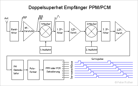 PCM - Pulse Code ModulationAbout in the middle of the eighties, the arrival of the affordable microprocessor techniques finally made it possible to protect the glitch sensitive part of the transmission chain from the pilot to the servo in the model against errors by special encoding. Of course this means that transmitter (encoding) and receiver(decoding) both need a processor to complete this task. These microprocessors have become extremely small, especially in the receiver (ca. 10 x 10 mm). The simple binary (two state) FSK-transmitter we were already using for PPM is perfectly suited to the task of transmitting 1 and 0 sequences. These digital messages are not restricted to just servo positions, but can contain additional information, checksums, failsafe values or even an identification of the model that is flown. Obviously one did not want to give up on the accuracy and frame rate of PPM. This was causing bandwith problems at first, too many bits needed to be squeezed in the 20-25 ms frame. PCM – lots of bitsPositions of sticks, switches and pots, originally analog voltages taken from a potentiometer or switch, are digitized by an Analog-Digital converter to an 8 to 10 Bits (256 to 1024 levels) number vor. For eight to ten servos already 80 -100 Bits. Add to this the 16-32 bit checksum per frame, synchronisation sequences and failsafe values , and a bit number of 100 -160 becomes necessary for a complete frame. A bit length of .3 ms (JR/Graupner and Futaba/Robbe) then produces a 30-48 ms frame time, considerably longer than the 22.5 ms PPM uses. If even more secure bit lengths and 12 channels are used, this time is increased to 55 ms, e.g. Simprop (System 90), where only 6 channels are proportional and 6 are switch channels. So everybody immediately realizes that decreasing the frame time, without data compression , not giving up on accuracy or reducing the number of channels, will not be possible. It should be said at this time that compression techniques as used by WinZIP, lha oder arj, able to compress large amounts of data in the computer world, cannot be used here. These programs look at the complete data set and construct a large (up to 1024 entries) table of "words". That way for instance a 10 byte "word" that occurs several times can be replaced with only 1 byte. With PCM, as in any other real-time transmission, the compression algorithm does not know what servo positions will occur ,and how often, in the next 3 minutes for instance, eventually replacing them with shorter bit sequences. PCM - transmissionActual PCM uses two systems to synchronize the transfer: an extra long starting pulse made up of so many "1" or "0" bits , that it can never be mistaken for data, or the so called Half bit pulse, e.g. 2,5 bits, equally impossibly mistaken for data. Usually this is followed by a synchronisation sequence, setting the receive-clock. This is the clock that scans the middle of the bits upon reception. This explains why , at the limits of the transmission range,with PPM (because of the overlaid noise) the servos are buzzing heavily, because the pulse flanks vary (up to+/-30 us), while PCM keeps them quiet, having half a bit (150 us) to play with, thus avoiding faulty interpretation of a bit. Next in line are the servo position data , usually in a few blocks, with variable contents. Then we have organisational data, like channel numbers or failsafe modus or failsafe values. Finally the checksum in the shape of a 16 bit long CRC (Cyclic Redundancy Check). It is the rest of the divison of the whole message by a 16th order polynom. This method is so secure that several hundred years could pass before an error goes unnoticed, while at the same time the calculation in the receiver processor is easily performed. Bit errors can be detected this way, but in no way corrected. This in turn means that , even if only one single bit error has crept in the ca. 100 -160 bits total frame length, the checksum fails and the whole message is rejected. The servo's remain in their last correctly received position until the arrival of new, correct data. If this takes too long (0.25-1 Sek), failsafe is activated in between: depending on the predefined settings a chosen (and defined in the transmitter) failsafe position or the last correctly received position. It is a large disadvantage that a transmission failure of one % causes a break in the complete link, but this could only be solved with more complicated and redundant encoding. An audio-CD is a good example: even a 17 bit wide scratch can go unnoticed, but 30 % more data (bits) is needed to make this possible. In our RC equipment the redundancy is provided by the high frame rate. The servo's cannot process more than 10-15 different positions per second. They receive about 45-60 pulses per second however. It is therefore not critical is a servo position has to be repeated because of a glitch. To reduce the failure time anyway, JR/Graupner (S-PCM) and Futaba/Robbe (PCM1024) subdivided the frame using separate CRC checks. This allows rejecting only a part of the faulty frame. But let's take a look at how the market leaders have conceived their PCM systems.
PCM - different systemsStructure of most actually used PCM systems JR/Graupner actually has 2 PCM systems on the market. Z-PCM (512) uses interlacing, e.g. every 21,77 ms channels 1 or 5, to 2 or 6, 3 or 7 and 4 or 8 gesendet, like 50 Hz half images on a TV screen that together give a 25 Hz full image. This would mean a frame rate of 2 complete frames for channel 1, or 43.5 ms. But if the data for channel 5 has not changed and the data for channel 1 is new, channel 1 will be sent in stead of channel 5, twice as fast or every 21,77 ms. Information about the channels that are actually transmitted in the received frame is of course also contained in the data. Accuracy is nine bits. A bit error means no data for 21.77 ms . Putting the "fast" channels in the 1 to 4 block and the slower ones in the 5-8 block allows optimal use of the command chain. S-PCM (1024) from JR/Graupner is a development of the previous system. To reduce downtime, smaller blocks of 10.65 ms are constructed. Four of these make up a complete 44 ms transmission message, providing data for each servo twice (21.30 ms frame). Accuracy is ten bits. Simprop PCM (System 90) uses a direct approach. A frame lasts 55 ms and contains 6 data blocks with eight bits for every proportional channel and three bits for every switch channel. Every block, in this case every channel,is secured separately, no need to reject the whole frame in case of errors. The less powerful securisation by a parity bit overlooks "double" errors, but these are exceptional anyway. Multiplex had a PCM System, that is no longer produced. An "improved" PPM called IPD (Intelligent Pulse Decoding) is used instead. Robbe Futaba PCM 1024 uses an interesting solution, yielding the fastest frame rate. Differential encoding reduces the number of bits per channel for 2 frames from 20 (2*1°) to 14 (10+4) , reducing the frame rate to 14.25 ms. In the first frame an absolute value is sent , in the second one only the relative change.A complete transmission message , every channel 2 times, lasts less than 30 ms in this case. A bit error causes a 14.25 ms block to be rejected. Accuracy is ten bits.
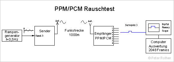 PCM and PPM MeasurementsI have analyzed JR/Graupner Z-PCM and Futaba/Robbe PCM 1024 by means of a Code Analyzer / Memory Digital Scope. Both systems are mature and is was not possible to cause them to produce bad servo pulses by bad synchronisation or superimposed noise; thanks to the CRC check of course. Even though lots of bits have to be transmitted without errors , these systems completed the "noise test" (range) with a better result than a very sensitive PPM receiver. Servo pulses on this receiver were almost unrecognizable before the F-149DP (Futaba/Robbe) PCM receiver needed to switch to "hold" in order to mask the failures. 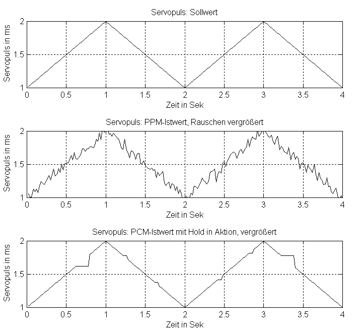 To record an eventual repeating of the pulse sequence (hold) with PCM, I replaced the control stick in the transmitter by a 0.5 Hz ramp generator,and registered servo pulse length digitally for PPM und PCM. Actual servo pulse lengths were plotted against the desired values and the differences recorded. The desired value was slowly changed from 1ms to 2 ms and back, within two seconds. Using an extremely weak received signal, PPM pulse length varied around the desired value by about 9 us on average (standard deviation). PCM pulses remained unchanged. This proves the general opinion that PCM has better range than PPM to be unfounded. PCM - conclusionsPCM-Modulation ,usually combined with excellent doublesuper receivers, provides the highest possible transmission security. What I consider a flaw in these systems is the missed opportunity of showing the quality of the transmission chain, e.g. a blinking LED for every missed frame while performing a "50 m-collapsed-antenna-test". This would make it possible to test security of the transmission before and after a flight. It would also be very easy, because the microprocessor is there already, to provide a channel selection by means of PLL. A "Black Box" in the shape of non-volatile memory ( very small, 8 pin EEROM) could continually record the number of glitches and their length together with signal strength. This could be read into a PC or displayed on the transmitter LCD screen on the field or at home. The recorded usage of the pilots channel or even the adjacent channels could also be interesting. PPM EvolutionImprovements can still be expected in the PPM sector, like the IPD system by Multiplex, Scan-PLL by ACT or Scan2000 by Simprop. Using a microprocessor in the receiver makes checking RC-pulses a possibility. Failsafe und Hold, exclusive advantages of PCM so far, are now also possible.The accuracy of PCM, especially at the limits of the tranmission range, cannot be equalled by PPM. If the error is small, not even the processor can differentiate between a correct or a false pulse. PPM will not be able to replace PCM completely. PCM – a plus for helicopters?Not less, but more spectacular crashes? This is a bit shortsighted: used properly, PCM can provide a substantial plus in security. A major disadvantage clearly is the fact that all kinds of glitching is masked by the very nature of the PCM system, making it impossible to recognize there is a problem present in the first place. So we should at least use the reactions of the receiver to missing or incorrect signals to increase safety. The worst case could be the one of an helicopter in stable forward flight , no longer obeying the commands of its pilot, and thus , with full power and perhaps ca. 1.800 to 1.900 RPM, flying towards the highway or a group of people. In this case, not at all uncommon, the survival of the heli must be secondary, it is much more important that it comes down as quick as possible, with the lowest possible rotor speed , as this the main danger for humans. There is an easy solution for this failsafe situation: programming throttle to idle, pitch probably on 1 to 20, should reduce the danger of the uncontrollable heli to a tolerable and reasonable level.Those of us that ever had to experience the incredible force of a rotor on full speed hitting a human being, can understand the kind of damage control in the largest sense the "throttle -to-idle" failsafe programming can provide. The fact that the heli itself will probably not survive this ordeal is totally meaningless, after all it is only a heap of metal, protecting a human from injury or even death is so much more important. With this simple specification the available properties of the PCM modulation can be optimally used in providing additional damage control. A comment by the author today: I am using PCM (Futaba/Robbe) and PPM equally in my electric gliders, but recommend PCM exclusively for helicopters. More affordable PCM receivers would make me use them for everything. |
|||
